
8 Different Types Of Gears And Their Applications
The humble gear is the unsung hero of modern machinery, allowing for the incredible advancements we see today. While many marvel at the wheel as a groundbreaking invention, it’s essential to acknowledge the crucial role the axle played in making it functional. Similarly, gears are what enable mechanical machines to operate seamlessly. The earliest recorded examples of gears hail from ancient China, dating back to the 4th century BC.
These relics can be found at the Luoyang Museum of Henan Province. In Europe, the oldest preserved gears date from around 150 BC and were part of the Antikythera Mechanism, a device designed to track astronomical positions. Roman Empire engineers also employed gears in their works, with mentions of them appearing in Alexandrian school texts during the 3rd century BC. Notably, Archimedes made significant contributions to gear development during this period.
Today, there’s an array of gear types, each boasting unique benefits and applications. Before delving into the various types of gears used today, it’s essential to understand how they’re manufactured. This article will explore the process and introduce you to eight commonly used gears.
Gear Machines
Gears serve as the backbone of machinery, enabling devices to function smoothly. However, the manufacturing process of gears itself relies on sophisticated equipment. Computer Numerical Control (CNC) gear machines are the ideal tools for producing a wide range of gears. These versatile machines can handle various cutting processes such as milling, grinding, broaching, and hobbing, allowing users to create specific gear types.
For those looking to produce gears, investing in a CNC gear machine is an excellent decision. A gear hobber is a particularly useful machine that excels at creating teeth by precision-cutting into a workpiece. Its operation revolves around rotating the two spindles’ shafts and cutting into the material, making it suitable for processing various materials, including metal, wood, and plastic.
Gear hobbers are available in both vertical and horizontal configurations, with most models capable of producing gears up to ten feet in length. The range of sizes also varies, from light machines ideal for cutting diameters of up to 40 mm to heavy-duty ones designed for cutting diameters of up to 100 mm. Additionally, the market offers a variety of CNC gear machines, including broaching machines, bevel gear cutting machines, and gear shaving machines.
While new machinery can be pricey, second-hand alternatives from reputable brands are available at a lower cost. These pre-owned machines are in excellent working condition, offering similar performance to brand-new models but with a more affordable price tag. Now, let’s explore the most common types of gears used in various applications.
Spur Gears
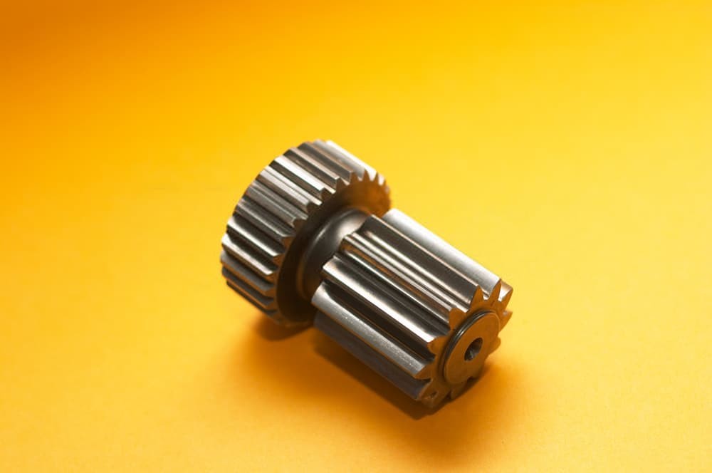
Spur gears, also known as straight-cut gears, form the most fundamental type of gear. Their design is characterized by a cylindrical shape with radially projecting teeth that are not straight-sided. Instead, they often feature involute or cycloidal tooth profiles. The edge of each tooth is straight and parallel to the rotation axis. For optimal meshing, spur gears must be paired with parallel shafts.
A notable advantage of spur gears is their ability to operate without generating axial thrust due to tooth loads.
While spur gears can exhibit significant noise when used at high speeds in machinery, this is largely attributed to the abrupt contact between teeth across their entire width, which generates stress and corresponding noise. However, they are well-suited for moderate and low-speed applications where their simplicity and effectiveness make them an attractive choice.
Helical Gears
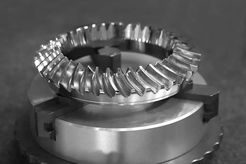
Helical gears, also known as dry-foxed gears, represent a refined version of spur gears. The defining characteristic of helical gears is the angled tooth design, which deviates from the linear alignment found in traditional spur gears. This unique curvature gives rise to the name ‘helix’ due to its resemblance to the shape of a spiral.
Double Helical Gears
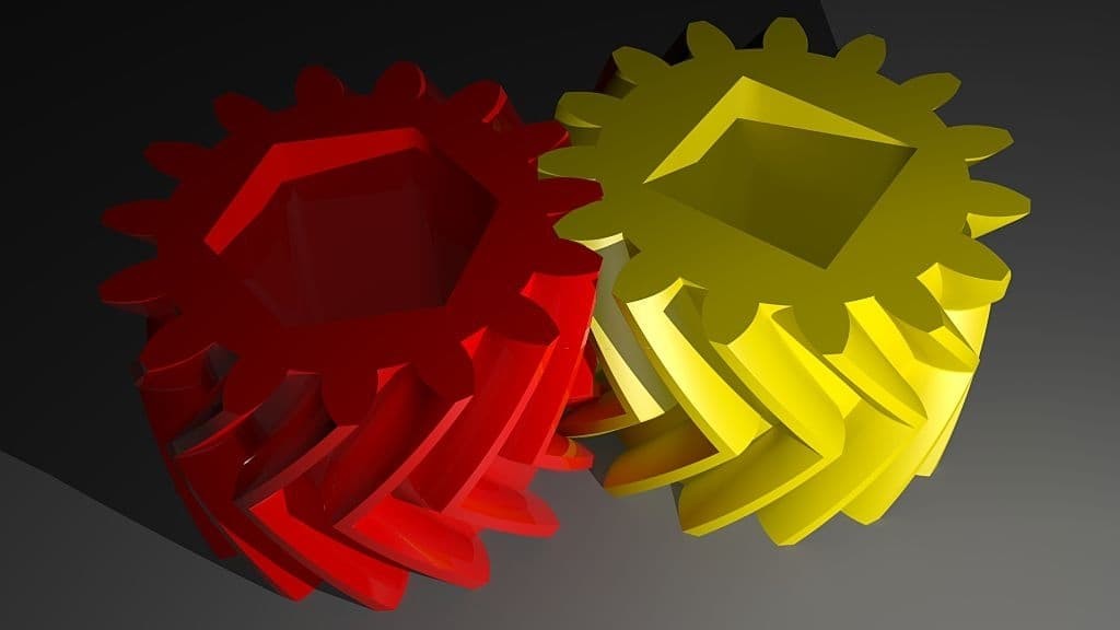
Double helical gears, also known as mirroring helical gears, consist of two identical gears that share the same axle. This design allows for the mitigation of axial thrust issues commonly associated with standard helical gears. The unique arrangement of teeth on these gears, which slant in opposite directions, effectively cancels out total axial thrust due to the opposing forces exerted by each half of the gear.
This configuration also reduces the need for thrust bearings, although it does present a more complex shape that can make manipulation more challenging.
The rotational direction of helical gears can be arranged in two distinct ways. The first, stable arrangement orients the gear’s faces such that each axial force is directed towards the center of the gear. In contrast, the second, unstable arrangement directs both axial forces away from the gear’s center.
Regardless of the chosen arrangement, the total axial force remains zero when the gears align properly.
However, if misalignment occurs, the unstable arrangement can generate a force that may lead to disassembly of the gear train. Conversely, a stable arrangement generates a corrective force, and reversing the rotation direction reverses the direction of axial thrusts, causing the stable configuration to become unstable and vice versa.
A special type of double helical gear is the herringbone gear, which differs from standard designs in that it lacks a central groove. Instead, the two mirrored gears form a V shape when joined.
Cage Gears
Cage gears, also referred to as lantern gears or lantern pinions, feature cylindrical rods with teeth parallel to the axle, arranged in a circular pattern around it. The gear’s design bears resemblance to both a lantern and a birdcage, hence its alternative names. Each end of the assembly is held together by disks, with the rod teeth and axle positioned between.
This unique construction allows for efficient operation, as dirt can easily pass through the rods rather than becoming trapped and contributing to wear. Moreover, cage gears can be manufactured using simple tools, eliminating the need for complex milling or cutting processes; instead, holes are drilled and rods inserted. It is essential to note that cage gears should always be driven by a gearwheel, serving as the driven component rather than the driver.
While commonly used in clocks, cage gears also find application in windmills and other mechanisms. Interestingly, these gears were initially met with skepticism by traditional clockmakers before gaining widespread acceptance for use in turret clocks, where harsh working conditions drove their adoption. Today, many traditional domestic clock movements utilize cage gears.
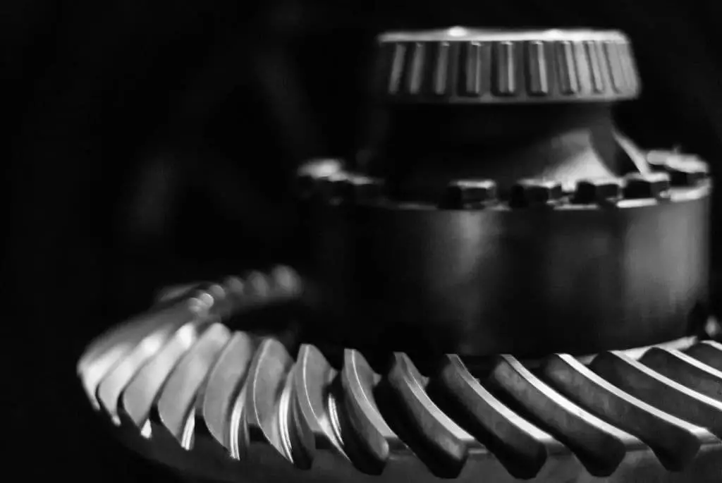
Bevel Gears
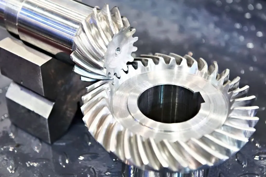
Bevel gears can be thought of as circular cones with cut-off tips that mesh together when their vertices occupy the same point. At this intersection, the shaft axes form a non-straight angle between 0 and 180 degrees, aside from miter gears which have equal teeth at 90-degree angles. Straight bevel gears are typically used at low speeds below 5 meters per second. A specific type of bevel gear is spiral bevels, which can be manufactured in different ways.
For instance, Gleason spiral bevels feature non-constant tooth depth, while Curvex and Oerlikon spiral bevels have constant tooth depth. Additionally, epicycloidal gears like Klingelnberg Cyclo-Palloid provide a unique manufacturing approach with constant tooth depth.
Hypoid Gears
Hypoid gears, while visually similar to spiral bevel gears, exhibit a crucial difference: their shaft axes do not intersect. Instead, the hypoid gear’s shape is actually a hyperboloid of revolution, compensating for the offset shaft. Typically, hypoid gears operate with shafts aligned at 90 degrees. This unique design enables a more gradual and smoother tooth contact compared to spiral bevel gears, contingent on the teeth’s angling and the direction of shaft offset.
A notable characteristic of hypoid gears is their sliding action along meshing teeth while rotating, necessitating robust lubrication to prevent tooth extrusion. In contrast to spiral bevel gears, hypoid gear pinions can be designed with fewer teeth, permitting gear ratios as high as 60:1 or greater. This advantage makes hypoid gears a popular choice for motor vehicle drive trains, where non-hypoid gears would generate excessive vibration and noise.
Worm Gears
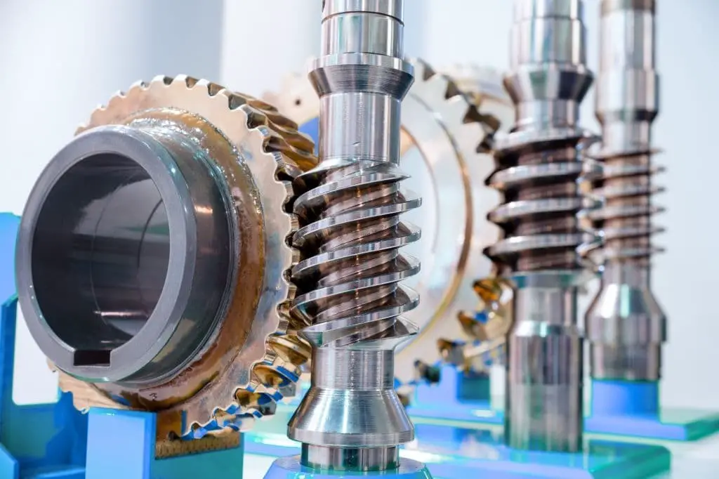
Worm-and-gear sets consist of a ‘worm’ – resembling a screw – and a ‘worm wheel’ that looks similar to a standard spur gear. This compact combination allows for high torque and low-speed gear ratios, unlike helical gears which are typically limited to 10:1 or less. With worm-and-gear sets, you can achieve up to 500:1. However, there’s a potential drawback – significant sliding action that can slow down operations.
Worm gears, in fact, are a type of helical gear with distinct characteristics.
Their larger helix angle and longer axial body give them screw-like qualities. Unlike helical gears, worm gears have at least one tooth that persists for a full rotation around the helix, which can be either single-threaded or multi-threaded.
A crucial aspect to keep in mind is that with a worm-and-gear set, the worm will always be able to drive the gear. However, if the gear tries to drive the worm, it may not succeed – especially when the lead angle is small.
This is because the circumferential force component of the worm’s teeth may not be sufficient to overcome friction.
Worm gears can also be right or left-handed and can be modified for medium to high power transmission by partially overlapping the tooth shapes, known as ‘double-enveloping’ or ‘cone-driving.’ This requires both gears to be concave and joined at a saddle point.
Self-locking worm-and-gear sets are also available, which is beneficial when you need to position a mechanism by turning the worm and holding that position. These types of mechanisms can be found in some musical instruments and music boxes.
Magnetic Gears

Magnetic gears operate on a fundamentally different principle than traditional gears. Instead of relying on physical contact between teeth, magnetic gears use opposing magnets that repel each other as they come closer. This unique mechanism enables magnetic gears to provide a springy backlash, allowing for smooth pressure application regardless of the relative angle between the gears.
Furthermore, magnetic gears offer a noise-free alternative to traditional gears and maintain the same motion ratio.
Related Posts
To begin with, starting a pool cleaning business requires consideration of multiple factors. Meanwhile, refining your house cleaning routine demands identifying the most efficient deep cleaning hacks. On the other hand, choosing the right rain gear for effective work is crucial. Furthermore, aspiring to become a disaster restoration specialist necessitates a clear understanding of one’s career path.
Additionally, selecting the best dehumidifiers for basements in 2024 requires careful consideration. Lastly, finding a reliable home cleaning service is vital for homeowners seeking assistance.