What Is A Crimp Style Connector?
Crimp style electrical connectors are a method of joining electrical conductors or wires together by deforming a metal barrel around the wires using a crimping tool. The barrel tightly grasps the wires and creates a secure mechanical and electrical connection. Crimp connectors were invented in the early 20th century and became widely used by the 1950s with the introduction of standardized crimping tools and connectors by companies like AMP Incorporated (now TE Connectivity).
Crimp connectors provide a quick and reliable way to join wires together without soldering or wire nuts. They are very common in automotive, aerospace, industrial, and consumer electronics applications. The crimped metal barrel forms a gas-tight connection that helps prevent corrosion. Overall, crimp connectors offer several benefits over other wire joining methods, but require proper connector selection and crimping technique.
Types of Crimp Connectors
There are several main types of crimp connectors:
- Insulated vs. Non-Insulated – Insulated crimp connectors have an insulating material like plastic or rubber over the metal portion. This helps prevent shorts and shocks. Non-insulated connectors are just the bare metal.
- Splices vs. Terminals – Splices are used to join two wires together, while terminals attach a wire to a component like a circuit board.
- Male vs. Female – Male crimp connectors have protruding pins that fit into female connectors with receptacles.
Some common types of insulated crimp connectors include:
- Butt connectors – Used for splicing wires together.
- Ring terminals – Used for attaching wires to posts and screws.
- Spade terminals – Used for connecting wires to binding posts.
- Push-on terminals – Used for quick splicing by pushing onto wires.
Non-insulated connectors like ferrules are commonly used in electronics and automation applications. Choosing the right type of crimp connector depends on the specific needs of the application.
Crimp Connector Materials
Crimp connectors are most commonly made out of metals like copper, aluminum, and various alloys due to their malleability, conductivity, and durability.
Copper is one of the most popular materials used for crimp connectors, as it is highly conductive while also being corrosion resistant. Pure copper connectors provide optimal conductivity but can be prone to work-hardening if not properly crimped. (1)
Aluminum is lighter and cheaper than copper but not quite as conductive. Aluminum is alloyed with other metals to improve its hardness and tensile strength for crimp connectors. When used for power transmission, aluminum connectors need to be larger than copper to match conductivity.
Other common crimp connector alloys include bronze, brass, nickel, and tin-plated metals, which provide benefits like corrosion resistance or solderability. The specific metal alloy used depends on the electrical, environmental, and mechanical needs of the application.
(1) https://www.elecdirect.com/media/specsheets/Terminals-ElecDirect.pdf
Crimp Connector Sizes
Crimp connectors come in a range of sizes to accommodate different wire gauges. The wire gauge refers to the diameter of the wire conductor. Common wire gauge sizes used with crimp connectors range from 16 AWG (1.3 mm diameter) up to 250 MCM (127 mm diameter) for large power transmission cables.
The size of the crimp connector needs to match the wire gauge to ensure a solid mechanical and electrical connection. Using an undersized connector can result in a loose connection while oversized connectors waste space and material. Connector manufacturers provide size charts showing the wire gauge range each connector size can accommodate.
Some key dimensions used to identify crimp connector sizes include the wire barrel opening diameter and length. For example, a common insulated female spade connector sized for 12 AWG wire has a barrel opening of 3.7 mm and length of 19 mm. The mating tab length and thickness are also factors. Connector dimensions are tailored to different applications from automotive wiring to industrial control systems.[1]
Choosing the proper terminal size for the wire helps prevent poor connections and system failures. Connector suppliers offer a wide range of sizes with standard Crimp style connectors to meet various application needs.
[1] https://www.elecdirect.com/media/specsheets/Terminals-ElecDirect.pdf
Crimping Tools
There are two main types of crimping tools used for crimp style connectors – hand tools and hydraulic tools. Hand tools, sometimes called crimpers, are manually operated and rely on the user’s strength to apply pressure. They typically have interchangeable dies that allow crimping a variety of connector sizes and types. Common hand crimping tools include ratchet crimpers, hex crimpers, and plier style crimpers. Hydraulic crimping tools use fluid pressure and pumps to generate the crimping force. They enable high crimping force consistency and are well-suited for high volume production environments. However, hydraulic tools are more expensive and less portable than hand crimpers.
When selecting a crimping tool, considerations include the connector type and size, the required crimping force, production volume, and budget. Using the proper crimping tool with matched connector dies helps ensure optimal electrical and mechanical performance of the crimp. Both hand and hydraulic crimpers require regular maintenance like cleaning and lubrication. Operators should be properly trained on using crimp tools to avoid damaging connectors or producing bad crimps.
According to RS Components, interchangeable crimping dies enable hand tools to cover a wide range of applications from small gauge wire crimping up to large cable lugs. Hydraulic crimp tools generate up to 10X the force of ratchet style hand crimpers for heavy duty electrical connections. When selecting crimpers, key factors are application suitability, quality, ergonomics and cost.
Proper Crimping Technique
Using the proper technique when crimping wires is critical for creating a solid electrical connection. Here are the key steps:
1. Strip the wire correctly – Remove the insulation from the end of the wire using wire strippers, leaving the appropriate amount of bare wire exposed based on the connector type. Avoid nicking or damaging the wire strands.
2. Insert the wire fully into the connector – Make sure all wire strands are fully inserted into the connector barrel and touch the end. Do not leave any stray strands outside the barrel.
3. Select the proper crimping tool – Use the crimper specified for the connector type and wire size. Using the wrong tool can result in a bad crimp.
4. Crimp following manufacturer instructions – Position the crimper jaws over the connector barrel and squeeze firmly. Avoid over or under crimping. Test the crimp with a tug on the wire.
Following the proper wire stripping, insertion, crimping tool selection, and technique ensures optimal electrical connectivity and strength. Consult manufacturer instructions for crimping details. See this guide for more tips.
Testing Crimp Connections
Once a wire crimp connector is applied, it is important to test the connection to ensure it was done properly. There are a few common methods used for testing crimped connections:
Visual Inspection
The first step is always a simple visual inspection of the crimped connector. Check that the crimp is centered on the conductor and that there are no stray wire strands poking out. The crimp should also have a smooth, consistent crimp indent showing that adequate pressure was applied.
Pull Testing
A pull test measures the amount of force needed to pull a wire out of a crimped connector. This ensures the crimp is strong enough for its intended application. Various test methods are used including hanging weights off wires or using specialized crimp testers (citation). Pull testing should meet specifications based on wire size and terminal type.
Continuity Testing
Using a multimeter, continuity can be checked between the conductor and connector. This confirms there is a complete electrical path through the crimp with no shorts or opens. Any irregular readings could indicate a bad crimp that needs redone.
Properly testing crimped connections helps validate the crimping process and catch any potential issues. Both pull testing and continuity testing should be done on a sample basis for quality control.
Advantages of Crimp Connectors
There are several advantages of using crimp connectors rather than soldering:
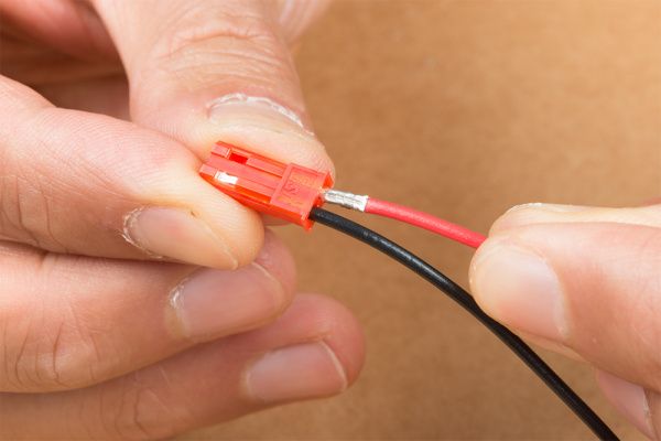
Crimp connectors are easy to use. No special skills are required. Simply insert the wire into the connector and use the proper crimping tool to crush the connector around the wire to form a secure connection. This makes installations much faster compared to the more meticulous process of soldering.
The crimp connectors are also reusable. If a mistake is made in the crimping, the connector can simply be removed and re-crimped. With soldered connections, reworking is difficult and usually requires completely removing and re-soldering the connection.
Additionally, crimp connectors are vibration resistant. The metal-to-metal contact provides a gas-tight connection that is not prone to cracking or weakening from vibrations like soldered joints can be. This makes crimp connectors well-suited for automotive, marine, and industrial applications where vibration is a factor.
Overall, the ease of installation, reusability, and durability of crimp connectors make them advantageous for many applications compared to soldering. Their vibration resistance also gives them an edge in mobile or high vibration environments.
Disadvantages of Crimp Connectors
While crimp connectors offer several benefits, they also come with some potential drawbacks to consider:
Crimp connectors require special crimping tools to make secure connections. Proper crimping tools can be more expensive than a basic soldering iron. Using the wrong tools can result in loose or faulty connections. According to R&F Industries, poor quality crimping is one of the main disadvantages versus soldering.
Over time, vibration and fatigue can cause crimped connections to come loose. The compressed metal tab loosens slightly within the connector. Soldered connections may maintain their integrity longer under these conditions. Regular inspection and maintenance is required to ensure reliable crimp connections as highlighted by Peigenesis.
Applications and Industries
Crimp style connectors are used extensively across many industries including automotive, aerospace, electronics, and electrical.
In the automotive industry, crimp connectors provide reliable and long-lasting electrical connections for wiring in vehicles. They are vibration resistant and can withstand the high temperatures found in automotive applications 1. Common uses in automotive include connecting wiring for lighting, ignition, sensors, and in-car entertainment systems.
Aerospace applications take advantage of crimp connectors’ lightweight, compact size, and reliability under extreme conditions. They are ideal for aircraft electrical systems and wiring. NASA standards require crimp connectors for space missions due to their durability and performance consistency 1.
In electronics and electrical devices, crimp connectors provide secure wire joins for both prototyping and production. They are extensively used in consumer electronics, appliances, power tools, and industrial equipment. Applications range from connecting integrated circuit pins to wiring electric motors.